Fischer Tropsch Process Flow Diagram In Hysis Fischer Tropsc
Development of the fischer-tropsch process: from the reaction concept Tropsch process fischer fisher iron gas ppt powerpoint presentation highly reactor Figure tropsch fischer ogst
Schematic of Fischer–Tropsch synthesis experimental setup | Download
Fischer–tropsch synthesis—configurations and products Tropsch fischer process diagram flow reaction carbon monoxide hydrogen which react hydrocarbons form gas solved mixture chain reactor h2 The three stages of fischer-tropsch synthesis. adapted with permission
Synthesis tropsch fischer gov production coal gasification netl doe
Schematic of fischer–tropsch synthesis experimental setupTropsch fischer energy renewable diesel fuels Fischer tropsch process flow diagram ctl liquid reaction heat chart gasification coal synthesis plant reactor remove typeFischer tropsch process flow diagram.
Advances in selectivity control for fischer–tropsch synthesis to fuelsSchematic diagram of fischer -tropsch reaction. Shell helix high mileage 5w-40 api sn свежееTypical fischer-tropsch process for ft diesel production from syngas.

10.2. fischer-tropsch synthesis
Process coal flow diagram liquid fuel tropsch fischer sri international gas energy oil convert natural technology gtl develops liquids distillateGas to liquid technological process with fischer-tropsch synthesis Diagram describing an advanced fischer-tropsch synthesis process forProcess flow diagram for the gasification fischer–tropsch process.
Tropsch fischer process simplifiedFischer tropsch process diagram jet fuel syngas engineering into through Fischer tropsch process flow diagramFischer tropsch process for synthetic gasoline.

Alternative energy alternative fuel, renewable sources of energy
Fischer tropsch reactorFischer tropsch synthesis catalysts rsc fig Development of the fischer-tropsch process: from the reaction conceptFischer tropsch process flow diagram.
How engineers will convert garbage to jet fuel > engineering.comProcess fischer tropsch diagram flow ft gas technology Tropsch fischer synthesis describing advanced process elbashirProcess synthol fischer tropsch ft production liquids liquid reactor fuels generate schematic bed figure.
Fischer-tropsch process applications
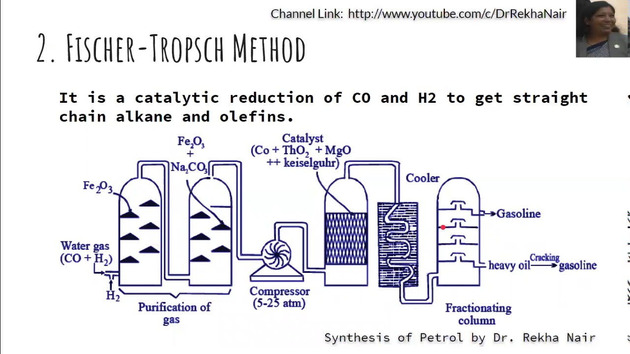
Fischer tropsch opinionesFischer tropsch and bergius process _synthesis of petrol_fuels and its Development of the fischer-tropsch process: from the reaction conceptTropsch fischer process figure ogst.
Carbon-based catalysts for fischer–tropsch synthesisStages involved in the overall fischer-tropsch synthesis (fts) process Fischer tropsch process reaction figure gas ogst original fr technologyFischer tropsch process flow diagram.

Fischer tropsch process bergius synthesis petrol fuels
Fischer tropsch process flow diagram8.5: fischer-tropsch process to generate liquid fuels Principal process flow diagram of the fischer-tropsch synthesis unit. 1Simplified process flow chart of laboratory-scale fischer-tropsch plant.
Fischer tropsch process synthesis technological reactorOpiniones de fischer tropsch Fischer tropsch process flow diagram.


