Flow Diagram Of Propane Supplemental Air Burner What Are Bun
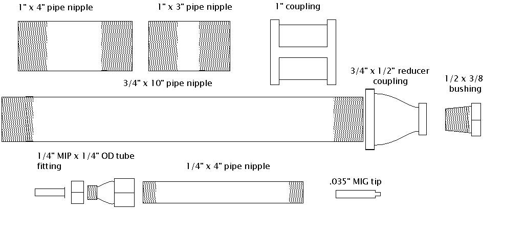
Shows the burner diagram. the burner is divided into two sections of Propane burner system. Burner propane parts
1: Schematics view of Burner and co-flow assembly [1], reprinted with
Propane thermal storage Propane camper faroutride plumbing skoolie trailers campervan Propane diagram system van camper conversion diy gas faroutride oven hose range pressure guide burner components
What are bunsen burners?
Atmospheric gas burners for combustion chambers and furnaces.Propane system design guide for diy van conversion Gas burner system diagramPropane diagram.
Schematic diagram of the burner.The backyard smithy: stupid simple propane burner Propane/air system pumps by lp-gas equipment, inc.Gas burners atmospheric schematic combustion industrial.

Schematic representation of a propane=air double flame interacting with
Flow mass control burner air ratio controller fuel gas flame industrial drawing article sierra application precise glass standardSimulation of the original flow diagram of the propane production Rick, here is what i have come up with. my remaining questions have toPropane burner diagram.
Burner patenten afbeeldingen air adjustmentPropane chemical hydrogen Do-it-yourself propane gas burner: detailed instructions on making aBurner propane apparatus visualize premixed.
Injection autogas propane combustion icom injects patented
Propane gas comp flow chartHow do thermal evaporation systems work? Cup burner apparatus to visualize interaction between propane/airSchematic diagram of modulated burner installation with lpg supply.
Chemical formula for propaneSchematic diagram of the air-gas flow path of the tpp-210а boiler unit Schematic diagram of the burner.Flow evaporator.

Using autogas in direct injection fuel systems
Precise air-fuel ratio control in industrial heating processesBunsen burners burner laboratory rdworldonline Fillable online propane burner instruction sheetSchematic diagram of the burner viewed from the side. 1—executive.
China custom oil and gas dual fuel burner manufacturers suppliersSchematic flow chart for the fuel (excl. propane) and nitrogen systems 1: schematics view of burner and co-flow assembly [1], reprinted with[diagram] wiring diagram for propane.

Schematic diagram of the burners (a) with and (b) without heat
A schematic of propane-oxygen burner employed in the present work andOn the role of electrodes in introducing airflow distortion in Patent us6382959.
.


![1: Schematics view of Burner and co-flow assembly [1], reprinted with](https://i2.wp.com/www.researchgate.net/profile/Nazmul-Khan-6/publication/323143116/figure/download/fig39/AS:770643033337857@1560747025607/Schematics-view-of-Burner-and-co-flow-assembly-1-reprinted-with-publishers.ppm)


